
| Home | Empennage kit | Wing Kit | Fuselage Kit | Finish Kit | Power Plant Kit | Avionics | Paint | Interior | Home |
|
|
|||||||||||
|
|||||||||||
| VERTICAL STAB | RUDDER | ANTI-SERVO TAB | STABILATOR | TAILCONE | EMP ATTACH | EMP FAIRINGS | BUILDERS LOG |
| Page 06.02 Vertical Stabilizer |
|
|||||||||||
|
Step 01: Read Section 5 and preview all assembly steps prior to construction |
Note: Step 2 through step 4 refer to Figure 1. In These steps you will fabricate a wedges that will assist you when blind riveting. |
|||||||||||
|
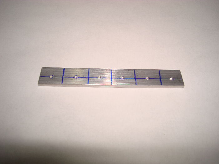
Step 02: Trim both of the
ears off the AEX Wedge. Builder Note: Ears cut off Marked to drill and cut. 07/03/10 |
 |
|||||||||||
|
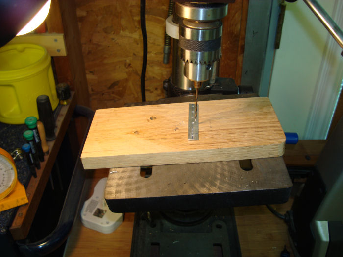
Step 03:
Beginning 1/4
inch from either end of the AEX Wedge, drill a hole every 1/2 inch using
a # 40 Drill bit. 07/08/10 |
 |
|||||||||||
|
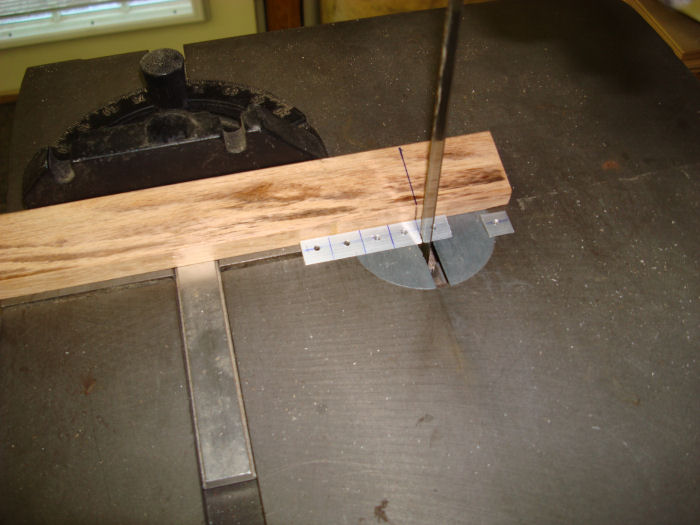
Step 04: Cut the AXE wedge
between each of the holes drilled in Step 3. You now have multiple wedge
tools to aid riveting when applicable 07/08/10 |
 |
|||||||||||
|
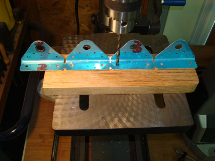
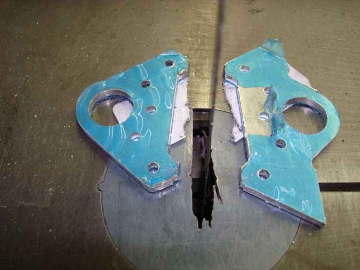
Step 05:
Final- Drill # 12 the 3/16 holes in the flange of the VS-1210 Hinge
Brackets called out in Figure 2. 07/08/10 |
 |
|||||||||||
|
Step 06:
Separate the VS-1210 Hinge Brackets by removing the material called out
in Figure 2. Separation is best done by cutting through the joining material and finishing the edge with a file . 07/08/10 |
 |
|||||||||||
|
Step 07: Mark the VS-1211 Hinge Spacers with the
VS-1211A and VS-11B part numbers as shown in Figure 3. Separate the
VS-1211A and VS-1211B by removing the material called out in Figure 3. 07/08/10 |
 |
|||||||||||
|
STEP 08: Cleco the
VS-1211A Hinge Spacer between two of the VS-210 Hinge Brackets.
Final-Drill #30 the 1/8" holes. Repeat Step 8 with the VS-1211B Hinge Spacer and the remaining two hinge brackets. 07/08/10 Builder Note: Add a slight bend to the clips to keep the top tight. |
 |
|||||||||||
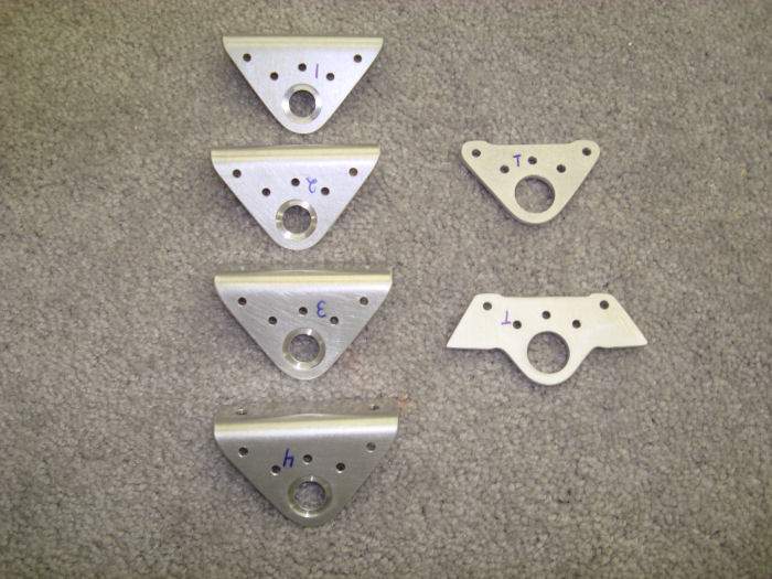
| STEP 08B:Mark the parts (
Section 5C ), to return them to the same position as drilled. Then
remove the clecoes and deburr ( Section 5B ) the edges and holes of all
four hinge brackets and both hinge spacers. ( 1 Through 4 ) Top to Bottom ( T ) Top Face Up Builder Note: Hold for Priming. 07/08/10 |
 |
|||||||||||
|
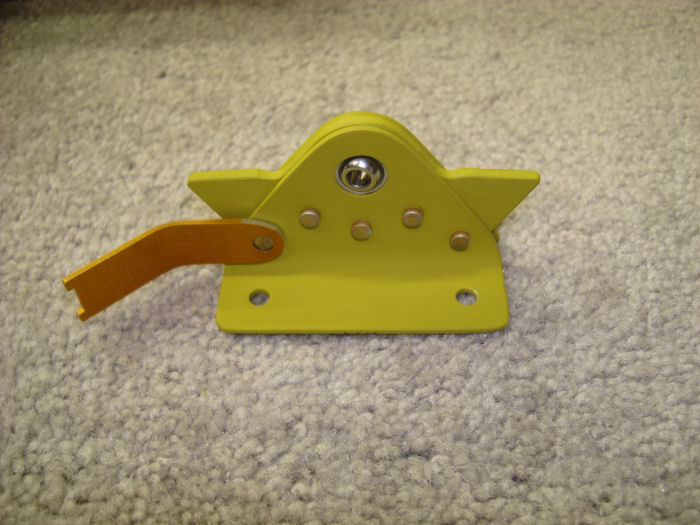
Step 09: Insert the called
out bearing into the largest hole in the VS-1211A Hinge Spacer.
Re-cleco, then rivet the hinge spacer between the two VS1210 Hinge
Brackets in the same position as drilled per call-outs in Figure 4. Builder Note: Primed all Vertical Stabilizer parts on 09/25/10 Start Final Assembly on 09/27/10 |
 |
|||||||||||
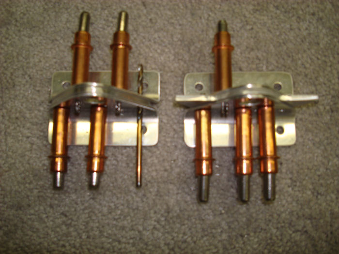
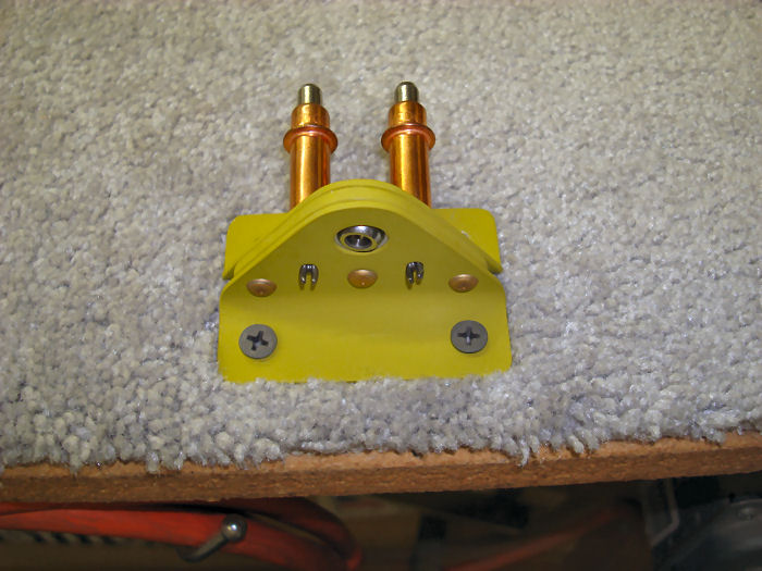
| Step 10:
Insert the called out bearing into the largest
hole in the VS-121B Hinge Spacer. Re-cleco, then rivet the hinge spacer
between the two VS-1210 Hinge Brackets in the same position as drilled
per call-outs in Figure 5. 09/27/10 Builder Note: Screws in work bench help when riveting |
 |
|||||||||||
| Page 06.02 Vertical Stabilizer |
|
| VERTICAL STAB | RUDDER | ANTI-SERVO TAB | STABILATOR | TAILCONE | EMP ATTACH | EMP FAIRINGS | BUILDERS LOG |
|
||||||||||
|
Disclaimer : Information contained on this Site may be out of date and /or inaccurate - Please Confirm any important data with a reliable source. |